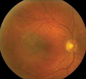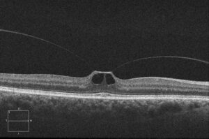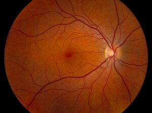
En face OCT reconstructs a retinal layer as a flat image, as if the surgeon looked at the retina from above at a chosen depth.
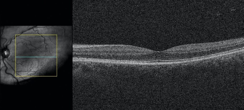
Standard B-scans show cross sections, but they sample only a thin line, and they may miss patterns that extend across the macula.
En face images fill this gap, and they show the shape and extent of lesions.
How En Face OCT Works
The device acquires a dense cube of A-scans, and software then slices the cube at a defined depth.
The slice can follow a retinal layer, such as the RPE, or a flat plane.
Because each slice covers the whole scan area, it shows the pattern of tissue at that depth.
Some devices produce en face images automatically, and others need manual adjustment.
Uses of En Face OCT in the Outer Retina
En face imaging shows the cone mosaic disruption in macular dystrophies and the ellipsoid zone loss in diseases such as macular telangiectasia (see ellipsoid zone disruption).
It also shows the extent of geographic atrophy and choroidal neovascularization, since the lesion appears as a map.
Outer retinal tubulations appear as branching structures in some slices (see outer retinal tubulation).
Fundus Explorer Pro
Photograph the retinal findings described here with the phone already in your pocket — 22 D optics and built-in illumination in one handheld unit.
From Choroida — the team behind this siteEn Face OCT in Vitreoretinal Disease
In epiretinal membranes, en face images show the folds and the contraction pattern.
In macular holes, the images show the hole diameter and the vitreous attachment.
Vitreous slices reveal the posterior hyaloid and the extent of vitreomacular traction.
En Face OCT and the Choroid
Mrejen and Spaide described how en face slices reveal choroidal vessels, vortex veins, and pachyvessels.
Slices through the choroid help to identify polyps, pachychoroid disease, and dilated vessels.
Therefore, en face imaging supports the diagnosis of central serous disease and polypoidal vasculopathy.
En Face OCT Angiography
OCT angiography uses the same principle, and it generates en face slices of flow.
Slabs for the superficial and deep plexuses show capillary dropout, and outer retina slabs show neovascular membranes.
Always correlate the slab with the B-scan, since segmentation errors can create false findings.
Pitfalls
- Segmentation errors that shift the slice to the wrong layer
- Eye movement causing stripes or doubled vessels
- Poor signal strength reducing detail
- Overreading normal variation as pathology
Check the B-scan for every en face finding, and adjust the slab manually when the boundaries look wrong.
An Example Case
A 61-year-old woman has distorted vision and a subtle epiretinal membrane on B-scan.
En face OCT at the vitreoretinal interface shows radial folds converging on the fovea, and the pattern of traction becomes clear.
The surgeon uses the map to plan peeling, and the images guide counseling about expected benefit.
Questions Clinicians Ask
Clinicians ask whether en face images replace B-scans, and they do not, because both views complement each other.
They also ask which slab to choose, and the answer is to start with automatic slabs and adjust when boundaries drift.
Because en face views need accurate segmentation, always verify the layers.
Pitfalls to Avoid
- Reading a flat slab without checking the cross section
- Using the same slab settings across all eyes without adjustment
- Overlooking tilt or curvature in myopic eyes
- Mistaking vessels in a slab for lesions when the slice crosses layers
Looking Ahead
Software will automate layer-specific analysis, and it will highlight patterns of disease.
Combined structural and flow images will show lesions with fewer steps.
However, clinicians still need to understand the basis of each slice.
Practical Points
Save en face images in the record alongside the B-scans.
Then compare maps over time, since changes in shape and size show disease activity.
Also note the layer and depth of each slab used.
Choosing Slabs
Start with automated slabs, such as the RPE or the choriocapillaris, and then adjust the depth by hand.
Use thin slabs for fine detail and thick slabs for broader patterns.
Also use flattened slabs in myopic eyes, since curvature distorts fixed-depth slices.
Documenting Findings
Record the slab depth and the finding in the chart.
Then compare the same slab in follow-up scans, since small changes in depth alter the image.
Finally, teach staff the naming of slabs, so that reports stay consistent.
Share unusual patterns with colleagues, because they build a library of cases.
Because each device names slabs differently, keep a short guide at the workstation.
Also review difficult cases in a weekly image conference.
For the latest studies, see the PubMed results for en face OCT.
Document what you see
Two smartphone imaging tools built for everyday clinic use — one for the slit lamp, one for the fundus.
From Choroida — the team behind this siteReferences
- Mrejen S, Spaide RF. Optical coherence tomography: imaging of the choroid and beyond. Surv Ophthalmol. 2013;58:387-429.
- Staurenghi G, Sadda S, Chakravarthy U, Spaide RF. Proposed lexicon for anatomic landmarks in normal posterior segment spectral-domain optical coherence tomography: the IN-OCT consensus. Ophthalmology. 2014;121:1572-1578.
- Spaide RF, Fujimoto JG, Waheed NK, et al. Optical coherence tomography angiography. Prog Retin Eye Res. 2018;64:1-55.
- American Academy of Ophthalmology. Basic and Clinical Science Course, Section 12: Retina and Vitreous. AAO; current edition.

Writes and reviews the clinical articles on Educate. Every post is checked against peer-reviewed sources before it goes live.